The structure.
Solid cross-sections and the relationship between components shape the design.

Carsten / The thinking behind I·ctra
Before there is a rack,
there is a question.
For Carsten, engineering starts with understanding how a structure behaves. How does vibration travel? Where does a frame move? What happens where two materials meet?
Follow that thinking through ITO’s physical testing, the PROTO-AS development study and the construction of KEO.
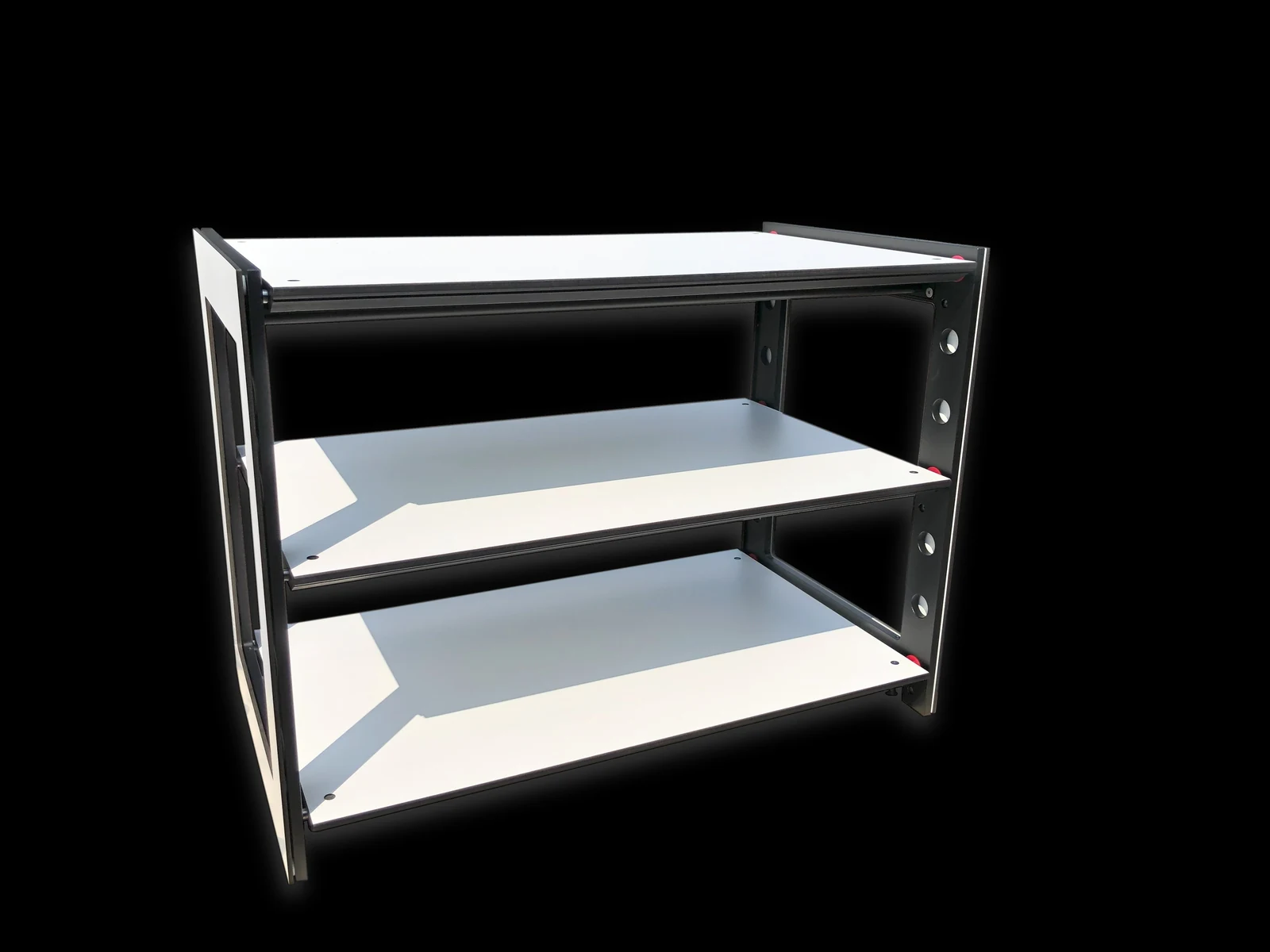
Solid cross-sections and the relationship between components shape the design.
Fewer separate parts and integrated functions are recurring design principles.
Material interfaces and internal damping are considered as part of the complete assembly.
01 / ITO physical testing
A dedicated vibration test rig applies repeatable signals to the ITO structure. Sensors record the input and the response at the upper shelf.
Measurements feed back into the development process, connecting the physical assembly with computer simulation.
Explore the setup, its recorded signals and the computer model. Each image identifies which stage it shows.
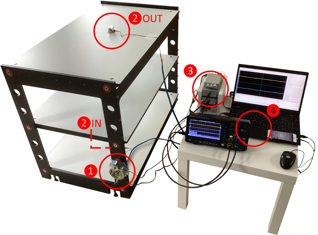
01 / 03 · Test setup
The shaker excites the frame while sensors record the input and the response at the upper shelf.
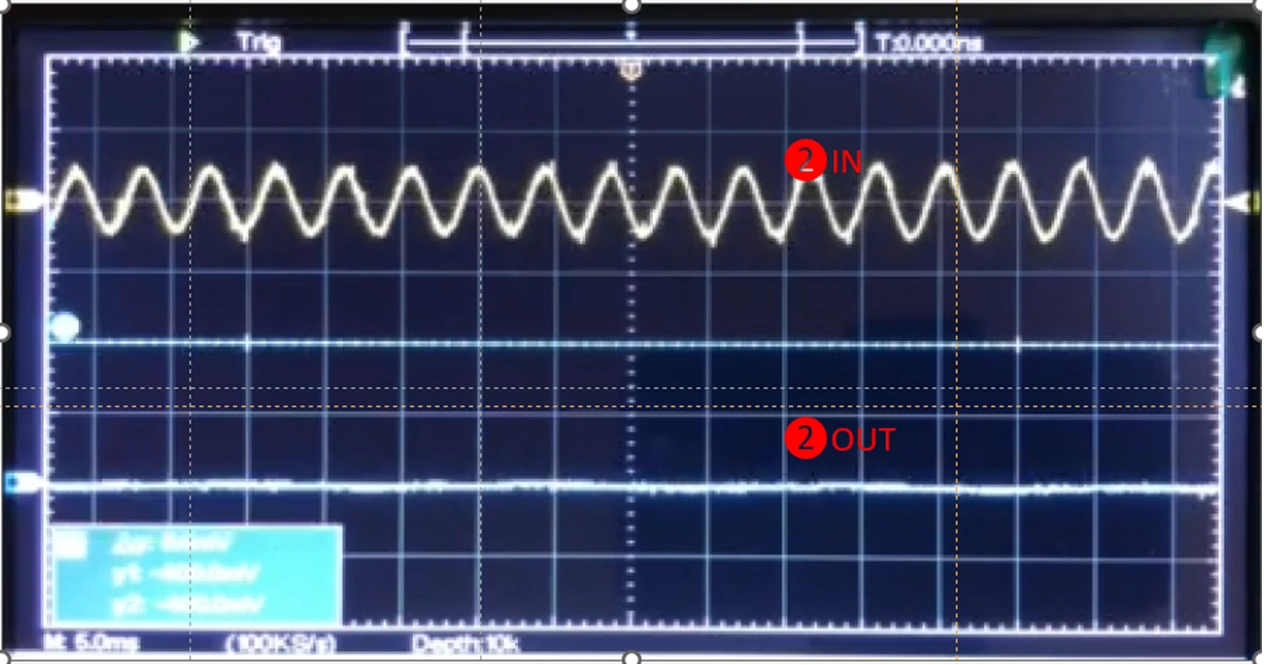
02 / 03 · Measured signals
The original oscilloscope display pairs the input at the frame with the response recorded at the upper shelf.
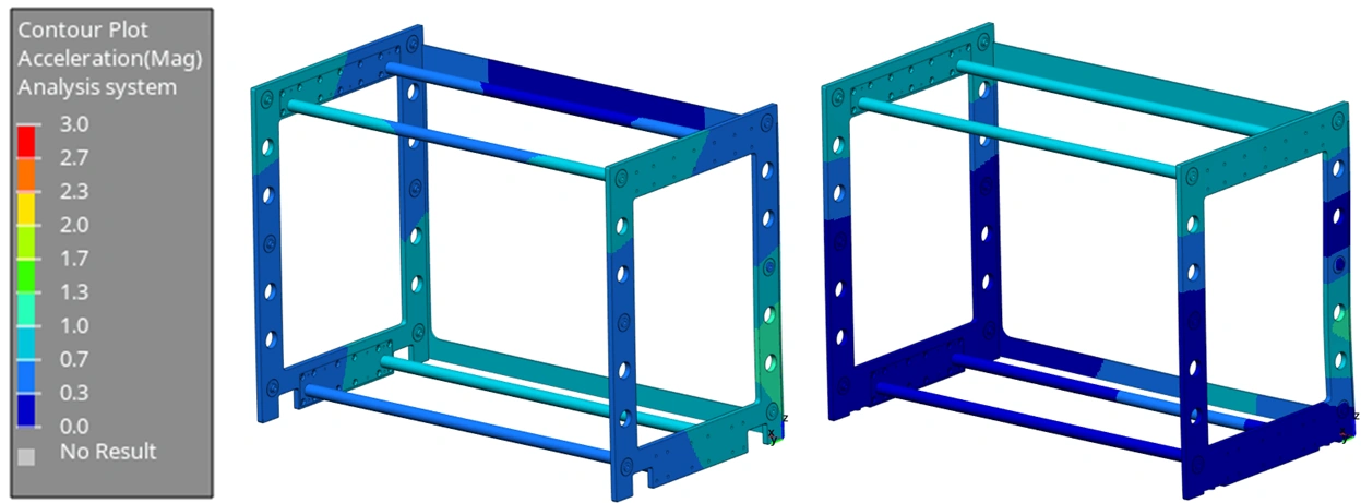
03 / 03 · Simulation
Computer-modelled frames show how structural response is studied during development. This image is a simulation, distinct from the measured signals.
02 / PROTO · ongoing development
A development study within the PROTO family.
The PROTO-AS study explores how the frame behaves, where vibration absorbers are positioned and how steel and aluminium meet. These analysis and construction views show the engineering questions being investigated.
01 / Modal analysis
Three views of the same model.
Modal analysis examines how the structure can vibrate. The colours show a simulated mode shape.
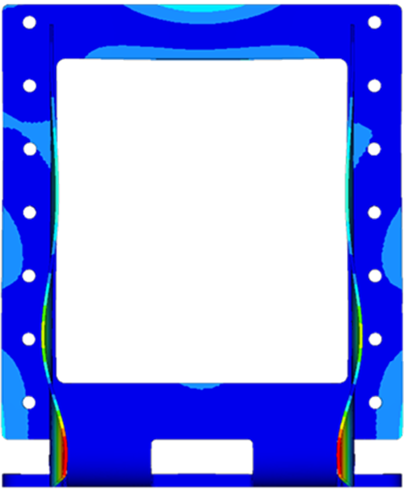
01 / 03 · Front view
Original modal-analysis visualisation from the PROTO-AS development study. The colours depict the simulated mode shape, not measured vibration reduction.
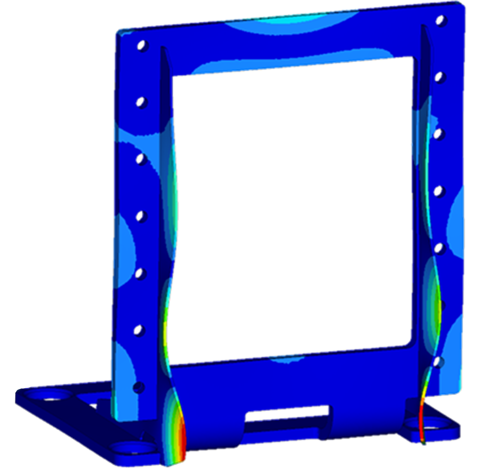
02 / 03 · Perspective view
Original modal-analysis visualisation from the PROTO-AS development study. The colours depict the simulated mode shape, not measured vibration reduction.
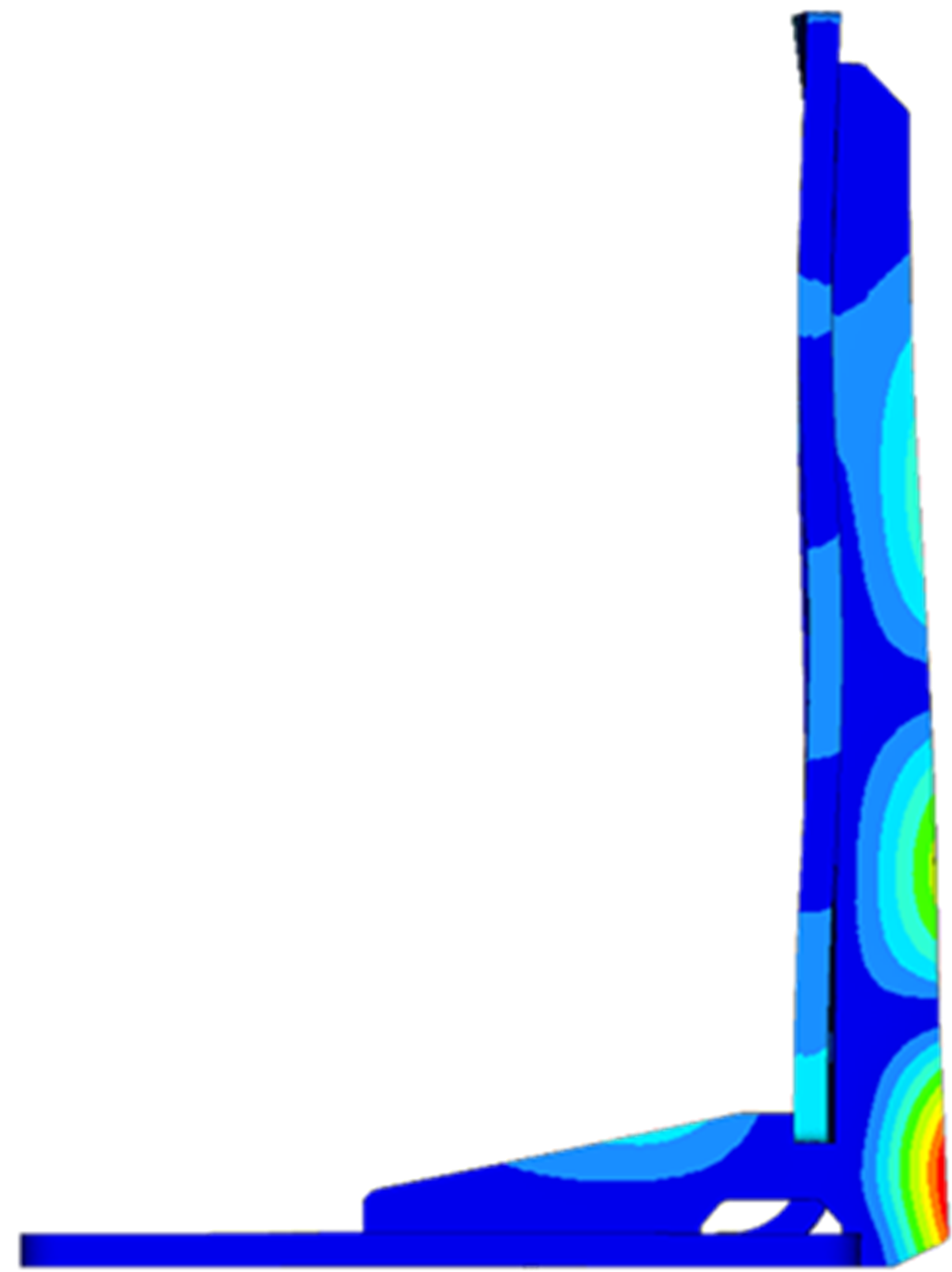
03 / 03 · Side view
Original modal-analysis visualisation from the PROTO-AS development study. The colours depict the simulated mode shape, not measured vibration reduction.
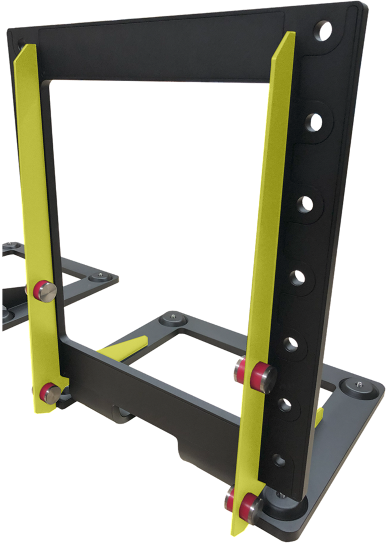
02 / Rear-fin construction
Locate the fins within the structure.
The rear-fin construction is shown alongside the analysis in the study. Switch views to highlight the fins.
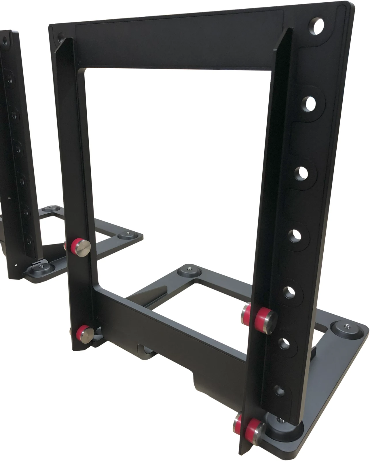
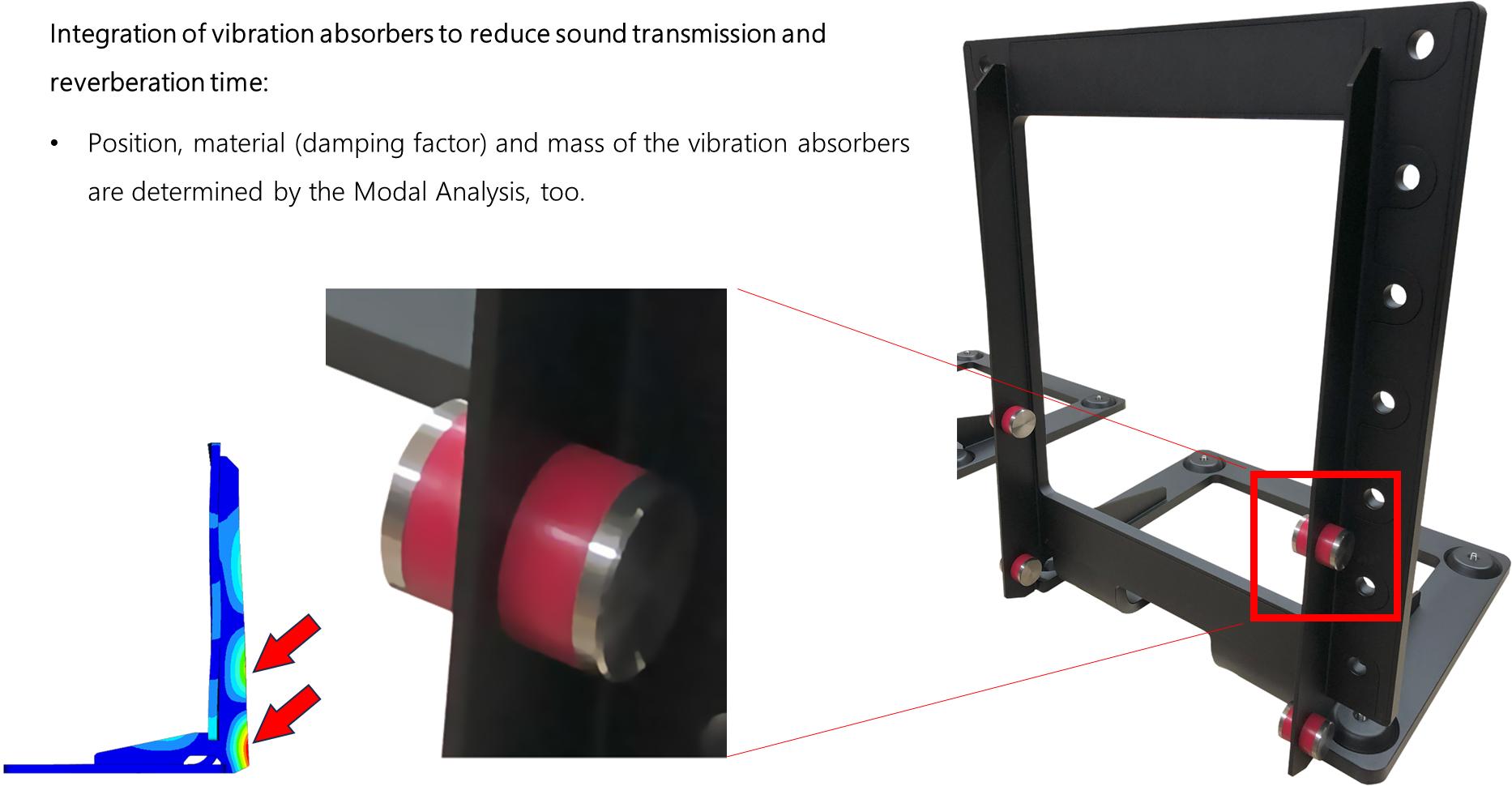
03 / Vibration absorbers
Position, material and mass.
Modal analysis informs these choices in the development study. The detail shows an absorber integrated into the frame.
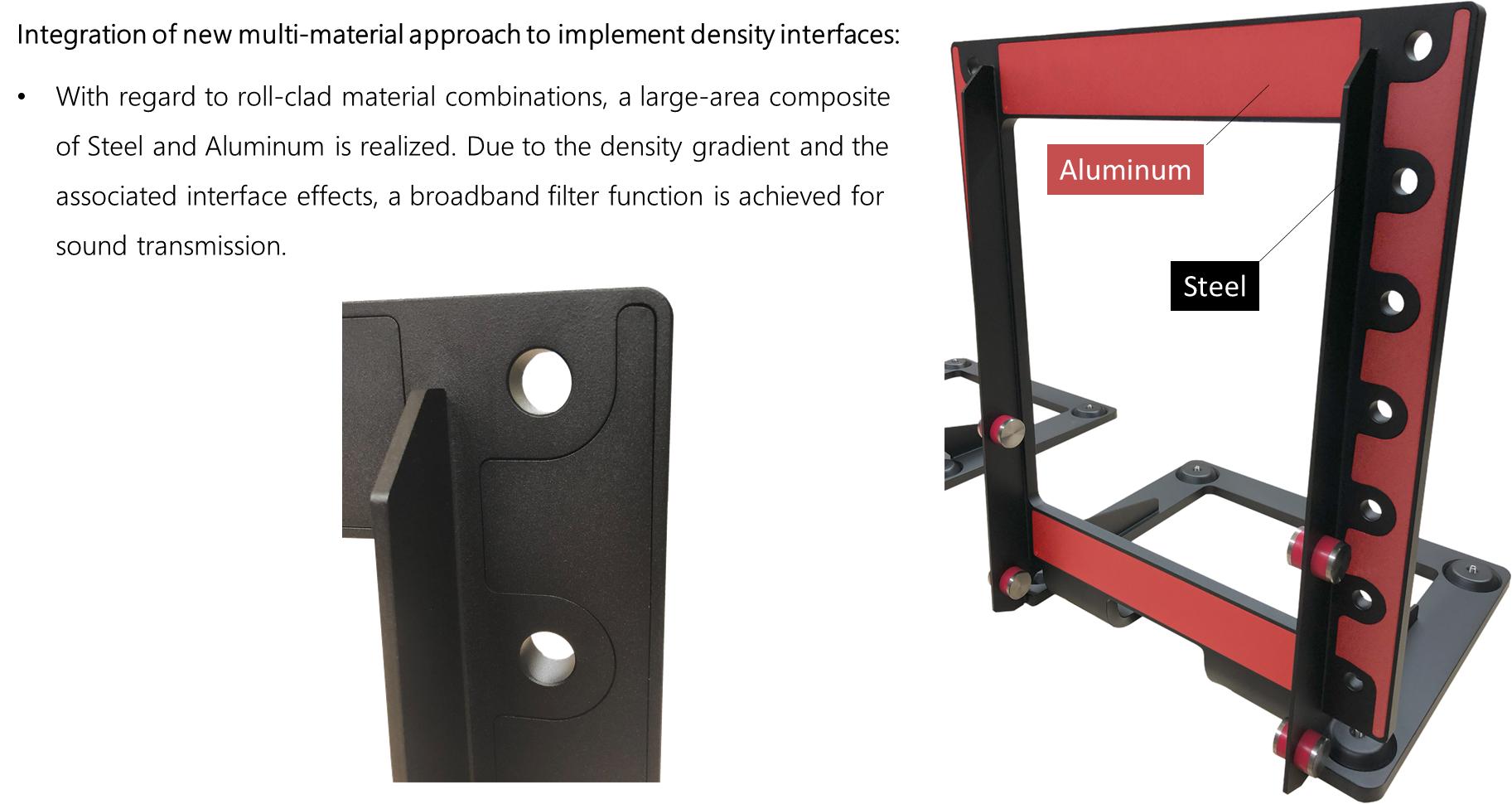
04 / Material interfaces
Steel and aluminium.
The study combines the two materials in the base structure and examines the interfaces between them.
Presented as “Ongoing Development / PROTO-AS” in the I·ctra engineering presentation, April 2026, slides 38–41. These images document a development study within the PROTO family.
05 / Cold bending
See the PROTO-AS base element take shape during cold bending.
03 / KEO construction & development
From the supporting beam to the complete rack.
Explore the supporting beam’s development, its shelf support and frame connections. Then see how these parts come together in the exposed structure and beneath the shelves of the complete rack.
01 / Structural development
Follow the supporting beam’s development.
The sequence explores the beam’s geometry. Switch to the development component to see its position within the frame, then compare it with the rack photographs below.
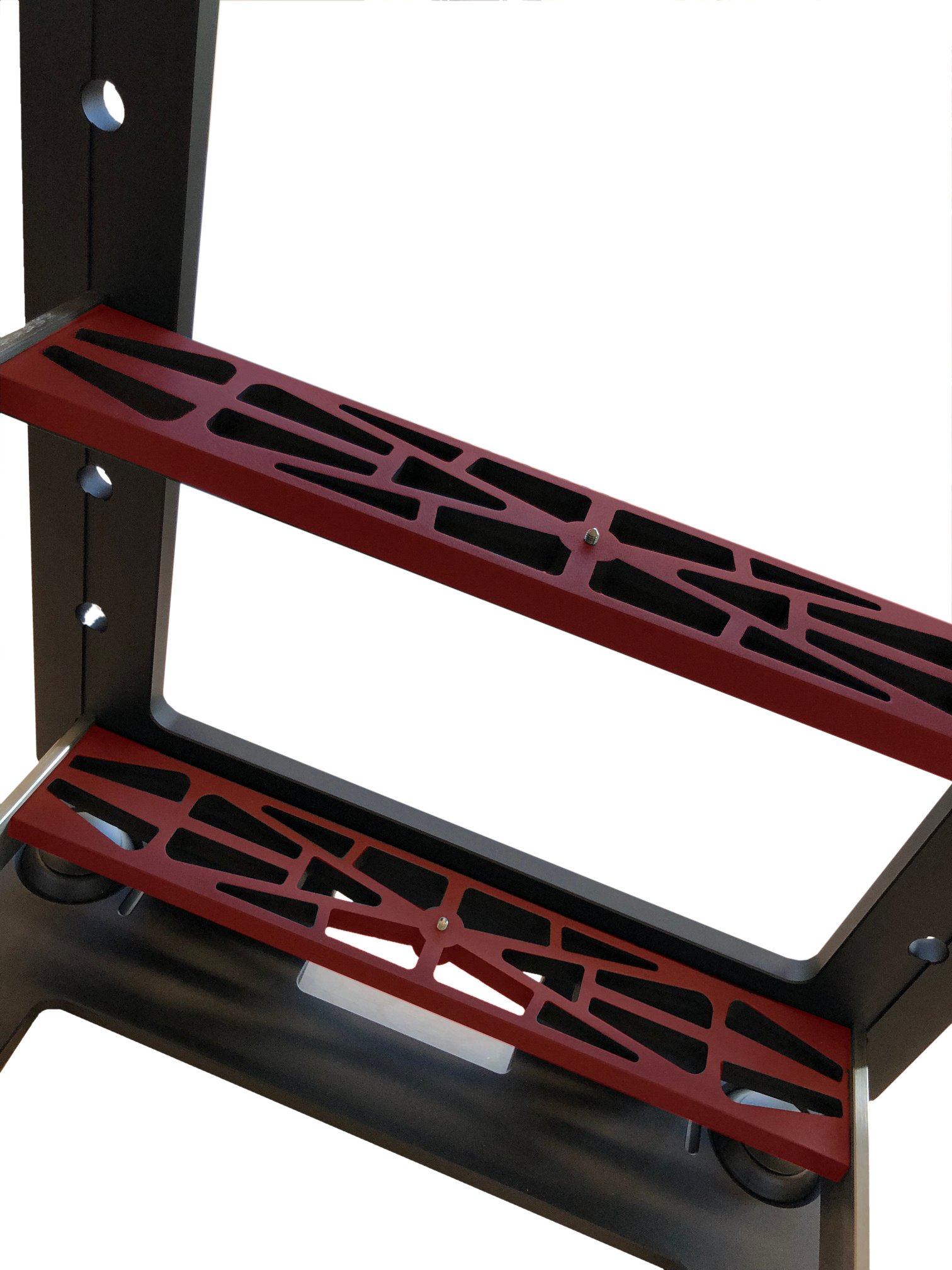
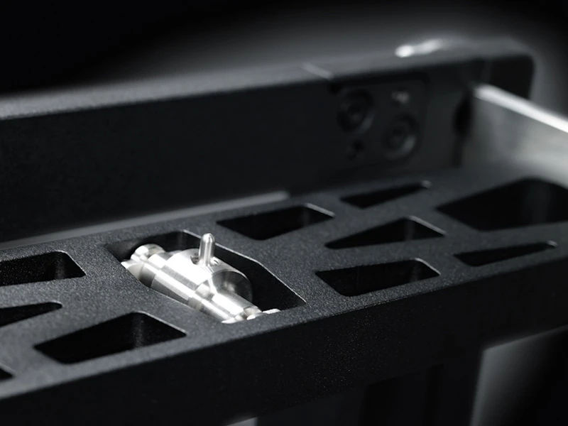
02 / Shelf support
A rocker within the beam.
KEO uses a four-point sub-chassis support with a freely rotating rocker and polymer inserts. The close-up shows the rocker mechanism integrated into the supporting beam.
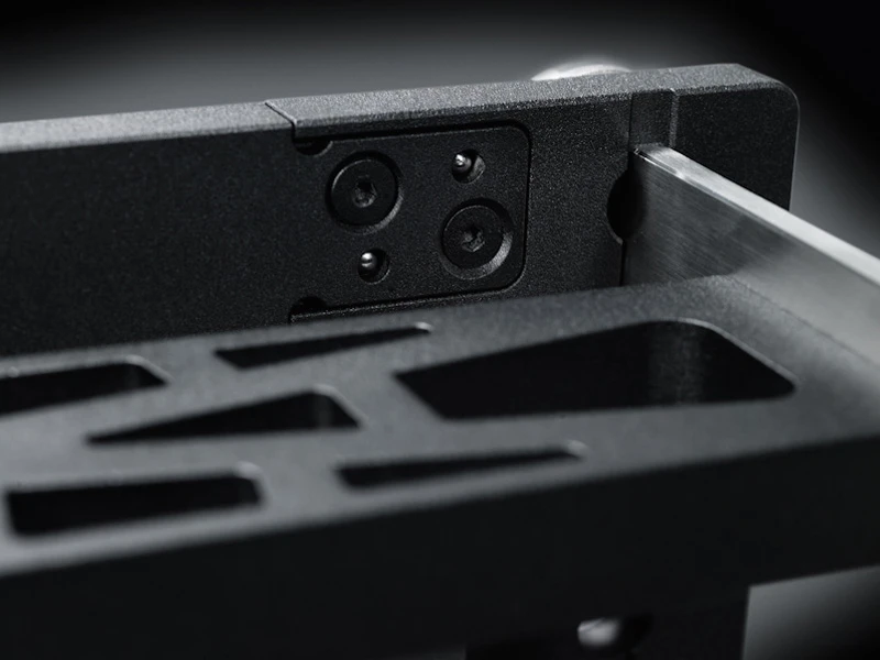
03 / Frame connection
Beam, support arm and upright.
This detail brings the connection into view: the supporting beam meets the frame, while the side arm extends towards the front of the shelf.
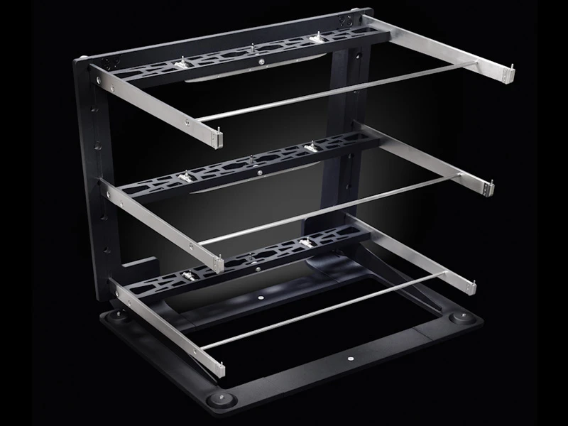
04 / The exposed structure
The same rack, with its shelves removed.
With the shelves removed, the three supporting beams and their connections are easier to follow. The side arms extend from the upright frame to support each shelf assembly.
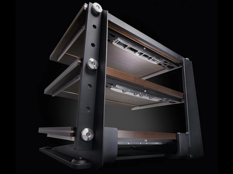
05 / The assembled rack
The beams, in place beneath the shelves.
This underside view shows the supporting beams within the assembled KEO. Their open geometry is visible directly below the wood-finished shelves.
KEO construction photographs and technical product information from I·ctra, shown alongside the structural development sequence.
Engineering presentation, April 2026; KEO construction photographs, technical product information and structural development sequence, supplied by I·ctra. Captions identify construction, measurement and simulation images.